Intersection in Constructive Solid Geometry
There are other dice besides six-sided dice, as any gamer knows. There are five “platonic” dice: the six-sider, the four-sider, the eight-sider, the twelve-sider, and the twenty-sider. “Platonic” means that the sides of the die are made up of evenly-sided polygons. But in role-playing games, you often end up wanting to generate a “percentage” roll, a number from 1 to 100 (or 0 to 99). There are two ways of doing this: a hundred-sided die, or two ten-sided dice. The hundred-sided die would end up being a sphere that never stopped, so people set out to make a ten-sided die. Not being mathematicians, they didn’t realize ten-sided dice don’t exist, and made one anyway.
Where the platonic dice can be made by constructing a union of simple polygons (a six-sided die needs six squares, a four-sided die needs four triangles, an eight-sided die needs eight pentangles), the ten-sided die isn’t nearly so simple. In Persistence of Vision, one relatively easy way to create a ten-sided die is to use the intersection of planes.
Intersections are part of the CSG system in Persistence of Vision, that is, “Constructive Solid Geometry”. We’ve already used difference and union in these tutorials. The intersection is just one more tool for making CSG objects. An intersection of two POV objects is that shape which is in all of the objects. It is the part where the objects overlap. The intersection of objects that don’t overlap at all doesn’t exist; the intersection of an object and itself is the object itself.
The intersection of two spheres
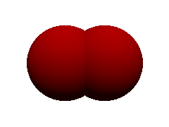
For example, we can take the intersection of two spheres to make a lens. Often, when making intersections, it will be useful to look at the union of the objects first. This is especially useful if you can’t see anything in your intersection, indicating that your objects don’t intersect at all. The union shows you where each part of your CSG really is.
[toggle code]
- #include "colors.inc"
-
light_source {
- <5,50,-50>
- color White
- }
-
camera {
- location <0,0,-3.5>
- look_at <0,0,0>
- }
-
background {
- color White
- }
-
union {
-
sphere {
- <-.5, 0, 0>, 1
- }
-
sphere {
- <.5, 0, 0>, 1
- }
-
pigment {
- color Red
- }
-
sphere {
- }
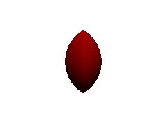
The union of two red spheres looks pretty much like what we’d expect two spheres to look like when they partially occupy the same space. Now, change the word “union” to “intersection” and see what happens:

[toggle code]
-
intersection {
-
sphere {
- <-.5, 0, 0>, 1
- }
-
sphere {
- <.5, 0, 0>, 1
- }
-
pigment {
- color Red
- }
-
sphere {
- }
You should notice two things. First, the shape now is only that part of the original image where both objects were. Second, there is a white line vertically down the center of the image. This is an annoying bug that occasionally shows up in raytracing when you are literally looking straight down the center of an object that is created with multiple objects. You can fix this by adding a very slight change to the camera location. Change the ‘x’ component of the camera location to .0001.
[toggle code]
-
camera {
- location <.0001,0,-3.5>
- look_at <0,0,0>
- }
By shifting the camera, the artifact disappears. Remember this if you are seeing something you don’t expect, that looks like you can see through your CSG object.
- Two overlapping spheres scene
- When setting up an intersection, it helps to use union to see where the objects overlap, first.
- Two spheres intersecting, straight on
- When using CSG, looking at something straight down its shared points can sometimes given strange results.
- Two intersecting spheres
- By moving the camera a tiny bit off-center, the strange artifacts disappear.
The inside and outside of planes
So you could make a nice magnifying glass or telescope using CSG and spheres. But you can do this intersection with any shape, and the shape we’re going to use use to make our die is the plane. Now, you might think that a plane, being infinitely thin, isn’t going to be useful for intersections. But you have to think like Persistence of Vision! I lied to you above: an intersection is not the place where both objects exist, at least not the way that we think of “existence”. Every object in Persistence of Vision consists of an “inside” and an “outside”. Usually, the “inside” of an object is the object itself, what you “see” when you render your image. The “inside” of a sphere is the sphere itself. The outside of the sphere is everything, well, outside of the sphere.
POV, however, never shows us the inside or the outside of anything, unless we cut into it. POV only shows us the surface of objects: the place where the inside and the outside meet. POV works in surfaces, not in solids. Slice through a sphere, and you’ll see that it doesn’t have anything inside it either, just like planes don’t have anything inside them.
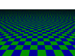
Planes simply make this behavior more obvious. The inside of a plane is everything underneath the plane. The outside of a plane is everything above the plane. We see that place where the inside and outside of the plane meet.
This behavior of planes is extremely important, so I’m going to show you what I mean about what you might expect and about what POV expects.
[toggle code]
- #include "colors.inc"
-
light_source {
- <5,50,-50>
- color White
- }
-
light_source {
- <5,-50,-50>
- color White
- }
-
camera {
- location <0,10,-30>
-
// location <0,-10,-30>
- look_at <0,0,0>
- }
-
background {
- color White
- }
-
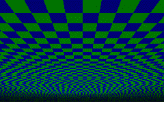
plane {
- y, 0
-
pigment {
- checker color Green, color Blue
- scale 2
- }
- }
We put two light sources here, one above the plane (y=50) and one below the plane (y=-50). Render the image twice, once with the first camera location, and once with the commented camera location (put two slashes in front of the y=10 location, and remove the two slashes from the y=-10 location; two slashes, if you’ll recall, “comment out” that line so that POV doesn’t use it).
You can see, very clearly, that in the first image we are looking at the plane from above, and in the second image we are looking at the plane from below. The plane appears to be paper thin (and in fact, it “appears” to be infinitely thin).
Now, make your plane part of a difference. We’ve already used the difference fairly extensively. I’ve described it as “gouging” one or more objects out of another object. What happens if we gouge a cylinder out of our infinitely thin plane? Since I’ve already told you about inside and outside, you might guess it isn’t going to just be a hole cut out of a piece of paper, but then what’s going to happen when you look at it from the bottom?
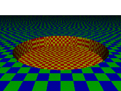
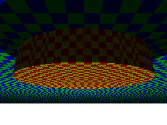
[toggle code]
-
difference {
-
plane {
- y, 0
-
pigment {
- checker color Green, color Blue
- scale 2
- }
- }
-
cylinder {
- <0,-5, 0>,<0, 5, 0>, 15
-
pigment {
- checker color Red, color Yellow
- }
- }
-
plane {
- }
Once again, render it twice, once above the plane, and once below. This gives you an idea of how POV really thinks of planes. Everything below the plane is “inside” of the plane, and is fair game for CSG objects. The visible part of the plane remains infinitely thin, however. When we look at the top of our difference, we see a cylindrical hole in the plane; when we look at the bottom, we see the cylindrical extension that we “dug out” of the plane.
Planes are weird. Normally you don’t see that, but it becomes obvious when you use constructive solid geometry on them.
- The topside of a plane scene
- From the top of the plane, we see what we expect: an infinitely extending flat surface.
- The underside of a plane scene
- From the underside of the plane, we see pretty much the same as the top, except that we now see the flat surface above us.
- Plane depression from above scene
- Taking the difference of a cylinder from a plane looks just as we’d expect from the top: a cylinder-like depression in the plane.
- Plane depression from below scene
- From below, the difference between a cylinder from a plane looks a whole lot more like a union. That’s because planes have insides, too, and when we look at an object in POV we’re looking at where the inside meets the outside.
And this has what to do with dice?
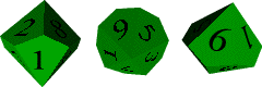
With the platonic dice, we could create regular polygons and glue them together using “union” (as I hope to do later to show you how to create a 12-sided die). We don’t have that option with 10-siders. A 10-sided die isn’t “regular” in that sense. All it really is is two five-sided “pyramids” glued together, as you can see in this image.
One way to create the image above would be to calculate the size of the four-sided irregular polygon needed to make each side. I have no idea what formula would do that for me. And it turns out to be fairly easy to make that die out of the intersection of planes.
An intersection of planes, if the planes all lie flat, is just going to be the bottom-most plane, since that is the only “shape” that includes all of the planes. But if you put any of the planes on an angle, you’ll end up with pyramid-like shapes.
[toggle code]
-
intersection {
-
plane {
- y, 0
- rotate <0,0,45>
- }
-
plane {
- y,0
- rotate <0,0,-45>
- }
-
pigment {
- checker color Green, color Blue
- scale 2
- }
-
plane {
- }
First thing to look at is that the ten-sider is obviously the union of two objects: it has a “top half” and a “bottom half”, with one half rotated a “half rotation”. So all we need to really do is make one half, and then invert it for the other half.
Each half has five “sides”. So instead of the intersection of two planes as we have above, we’ll use the intersection of five planes. And instead of typing them all out, we’ll just tell POV to “make five planes and rotate them”. This keeps open the possibility of easily using the same script to make, say, a 14-sided die or an 18-sided die should we want one.
[toggle code]
- #include "colors.inc"
-
light_source {
- <0, 10, -100>
- color White
- }
-
camera {
- location <0, 1, -2>
- look_at <0, 0, 0>
- }
-
background {
- color White
- }
- //configure our die's shape
- #declare diesides = 5;
- #declare dieheight = .5;
- #declare dierotate = -37;
- #declare siderotate = 360/diesides;
- #declare currentside = diesides;
-
intersection {
-
#while (currentside > 0)
-
plane {
- z, 0
- rotate <dierotate, 0, 0>
- rotate <0,siderotate*currentside,0>
- translate <0,dieheight,0>
- }
- #declare currentside = currentside - 1;
-
plane {
- #end
-
pigment {
- color Green
- }
- rotate <0,10,0>
-
#while (currentside > 0)
- }
We create a variable for the number of sides our “die halves” will have, a variable for the height of the tip of the die’s half, and a variable for how steep the die’s sides will slant. Then, we start counting down from the number of sides (five in this case) and make a plane for each side, rotating it first by the slant (dierotate) and then rotating it around the ‘y’ axis. What we’re going to end up with is a five-sided pyramid with its tip at ‘dieheight’ and its base infinitely low. At the end, we rotate the whole thing by 10 degrees around the ‘y’ axis, so that we can see the edges better.
This is our “top half”. The next thing we need to do is invert it vertically for our bottom half. The easiest way to do this is to put the whole top half into a variable, and then we can use the variable twice, for the top and bottom halves. Replace the intersection object with:
[toggle code]
-
#declare diehalf = intersection {
-
#while (currentside > 0)
-
plane {
- z, 0
- rotate <dierotate, 0, 0>
- rotate <0,siderotate*currentside,0>
- translate <0,dieheight,0>
- }
- #declare currentside = currentside - 1;
-
plane {
- #end
-
#while (currentside > 0)
- }
-
intersection {
- object { diehalf }
-
object { diehalf
- scale <1,-1,1>
- }
-
pigment {
- color Green
- }
- rotate <0,10,0>
- }
That’s close, and it would probably work, but in real life, for whatever reason, 10-sided dice don’t look like that. Add a “rotate <0, siderotate/2, 0>” to the bottom diehalf:

[toggle code]
-
object { diehalf
- scale <1,-1,1>
- rotate <0, siderotate/2, 0>
- }
If you need to, fool around with the “rotate <0,10,0>” so that you can see all sides and convince yourself that this is a 10-sided die.
- Ten-sided dice examples scene
- These ten-sided dice are what we want to end up with. It’s basically a regular shape, so we ought to be able to create it using a bit of scripting.
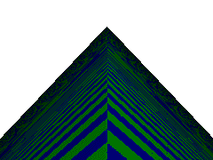
- Intersection of angled planes scene
- By taking the intersection of two angled planes, we end up with a pyramid-like object.
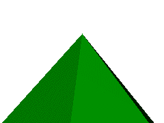
- Ten-sided die top half scene
- By rotating each angled plane a fifth of the way around a circle, we end up with a five-pointed pyramid.
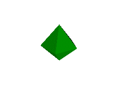
- Five-sided halves joined together scene
- By joining the five-sided pyramids together bottom-to-bottom, we end up with a ten-sided object, albeit one that doesn’t look quite like the ten-sided die in real life.
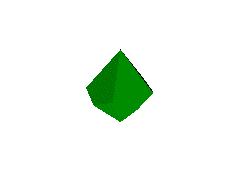
- Ten-sided die shape scene
- Rotate one of the five-sided halves halfway through its fifth-of-a-circle rotation, and we have the standard ten-sided die shape.
Bounding your CSG
Persistence of Vision tries to guess about what objects it doesn’t have to worry about. This way, it doesn’t need to do complex calculations on every pixel for objects that don’t matter for that pixel. In its guesses, it errs on the side of inclusiveness: it should never guess that an object does not matter when the object does matter, but it is okay to guess that the object does matter when it does not. Usually it guesses very well, but when you start using CSG, its guesses are often far too large. In fact, its guesses usually encompass the full shape of every part of the CSG object. For intersections (as well, often, as differences) this will include large areas that don’t really contain any part of the object.
You can drastically speed up your image’s rendering by telling POV where your object exists. You do this by setting the boundaries, or “bounds” of your object to be equal to another, simpler object. In this case, our die extends no further than dieheight above 0 on the ‘y’ axis, and no further than dieheight below 0 on the ‘y’ axis. We can tell POV that our die exists fully within a sphere of radius ‘dieheight’. The “bounded_by” keyword tells POV what shape to use as a bounding area.
[toggle code]
-
intersection {
- object { diehalf }
-
object { diehalf
- scale <1,-1,1>
- rotate <0, siderotate/2, 0>
- }
-
pigment {
- color Green
- }
-
bounded_by {
-
sphere {
- 0, dieheight
- }
-
sphere {
- }
- rotate <0,10,0>
- }
This doesn’t change the image at all if you’ve done it right. But it makes the image above render almost twice as fast.
That’s all you need if you just want the shape, or just want to fool around with intersections. But if you’re a gamer, you probably want to put some numbers on that die.
- CSG bounding example scene
- Done correctly, a bounded CSG object will look exactly the same as the unbounded object, but will render much more quickly.
Putting numbers on the die
I’ll use the same scripting that we used for the Spent Bullet Casing to put numbers on each face of the die.
There are two sets of numbers: the top, and the bottom, and they appear in a specific order. So we’ll make an array to hold each set, and then use “difference” to gouge those numbers out of our die. Note that in the calculations below I didn’t use any formula to determine how high to bring the numbers, I just used trial and error. When working with the ‘difference’, as with ‘intersection’, it is often useful to replace ‘difference’ with ‘union’ so that you can see where everything is. Once the placement is correct, change ‘union’ back to ‘difference’.
Replace the intersection above with the following. We’re going to make a ‘die10’ object, and then use that object in the “object { }” statement to place two d10’s in our scene.
[toggle code]
-
#declare die10shape = intersection {
- object { diehalf }
-
object { diehalf
- scale <1,-1,1>
- rotate <0, siderotate/2, 0>
- }
- }
- #declare top_numbers = array[5] {"0", "4", "6", "2", "8"}
- #declare bottom_numbers = array[5] {"7", "1", "9", "5", "3"}
-
#declare die10 = difference {
- object { die10shape }
- #declare currentside = diesides;
-
#while (currentside > 0)
- #declare topnum = top_numbers[currentside-1]
- #declare botnum = bottom_numbers[currentside-1]
- //the top numbers
-
text {
- ttf "timrom",
- topnum
- dieheight/10, 0
- translate <-.25,0,0>
- scale .35
- scale <-1,1,1>
- translate <0, 0, dieheight/1.6>
- rotate <dierotate,0,0>
- translate <0, -dieheight*.3,.08>
- rotate <0,-siderotate*currentside,0>
-
pigment {
- color Black
- }
- }
- //the bottom numbers
-
text {
- ttf "timrom"
- botnum
- dieheight/10, 0
- translate <-.25,0,0>
- scale .35
- scale <-1,1,1>
- translate <0,0, dieheight/1.6>
- rotate <-dierotate,0,0>
- translate <0, -dieheight*.18, -.1>
- rotate <0, 180-siderotate*currentside,0>
-
pigment {
- color Black
- }
- }
- #declare currentside = currentside - 1;
- #end
-
bounded_by {
-
sphere {
- 0, dieheight
- }
-
sphere {
- }
- }
-
object { die10
-
pigment {
- color Green
- }
- translate <.5,0,0>
-
pigment {
- }
-
object { die10
-
pigment {
- color Red
- }
- rotate <0, 105, 0>
- translate <-.5, 0, 0>
-
pigment {
- }
We take each number and translate it slightly to the left to center it. If you are using POV 3.5 or MegaPOV, you can replace ‘translate <-.25,0,0>’ with the ‘align_center’ keyword to automatically center each number. We scale it down so that it is the right size for our die, and then invert it horizontally, because otherwise the numbers will be backwards. We then move it out along the ‘z’ axis and rotate it up (or down) around the ‘x’ axis; then move it back down and slightly in. Finally, we rotate it around to the correct face.
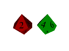
- Ten-sided die with numbers scene
- The text object can create numbers, and we can rotate each number around the sides of the die.
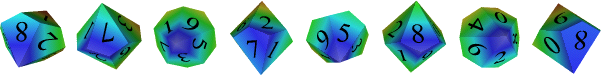
- Ten-sided dice banner scene
- As with any POV object, once you have the basic shape you can recreate it as much as you want in many variations.
Related Pages
